by Brian Coles
Most current methods of modeling hydraulics in Horizontal Directional Drilling (HDD) operations ignore the effect of cuttings loading on annular pressure losses. The accurate prediction of cuttings loading based on fluid properties, pump rate, cuttings size, bore geometry, and eccentricity is extremely difficult to achieve without computer modeling. This paper will address some of the issues with solids loading and show the results of computer modeling of annular pressure losses with and without considering the solids loading.
Computer software was used to model annular hydraulic losses with and without consideration of the cuttings loading and cuttings size while varying fluid properties, pump rate, bore geometry, and eccentricity.
The data from the modeling shows trends in annular hydraulics with changes in the various parameters, but it also shows that each bore may be significantly different. The data underscores the complex interactions of the various parameters.
While trends in the modeling exist, each bore will have different driving parameters and should be evaluated separately based on the limiting conditions. Computer modeling should be part of the preplanning and execution of critical bores and the effect of cuttings loading should not be ignored.
Horizontal Directional Drilling (HDD) projects have become more and more complex in recent years and are by their nature subject to greater scrutiny than open trench installations. The technology and methodologies used are suited to situations where natural or man made barriers prevent conventional installations. In many cases these barriers present constraints that prohibit any uncontrolled fluid returns to the surface (fracing out) or fluid communication with other nearby structures.
In an effort to reduce the risk of fracing out, adaptation of the hydraulics programs and equations used in oilfield applications are being applied to HDD applications in an effort to reduce risk and help ensure a better chance of success. These programs and equations are designed to take into account the annular pressure losses due to frictional pressure while pumping and the hydrostatic pressure. They take into account fluid density, rheological properties, bore geometry, length of the bore, and depth of the bore. They do not take into account the effect that cutting loading has on the total annular pressure. The reason is primarily that there is a complex relationship between pump rate, cuttings diameter, fluid density, fluid rheological properties, angle of the bore, and rate of penetration.
This paper will use the results of computer modeling to examine the effect that cuttings loading has on the total annular pressure. It will show how accounting for the effect of cuttings loading can contribute to a successful bore where hydraulics models that only account for annular pressure losses can give a false sense of security.
The modeling addresses two phases of the HDD operation:
These two operations were selected because they represent the two most common times when problems occur during the boring operation; the pilot bore because it has the most constricted annular space, and thus has potential for the highest annular pressure losses and the final ream because it has a high potential for excessive cuttings loading.
The properties used for modeling the pilot bore are shown in Table 1. The "Normal Fluid" is representative of a fluid that would be commonly mixed and pumped for an 8 inch diameter pilot hole. The "Thicker Fluid" is characteristic of a fluid used where hole cleaning or other issues have developed. These properties are not recommended for a particular fluid or situation, but are intended to be used for modeling purposes only. Requirements for each bore should be based on local conditions and good drilling practices.
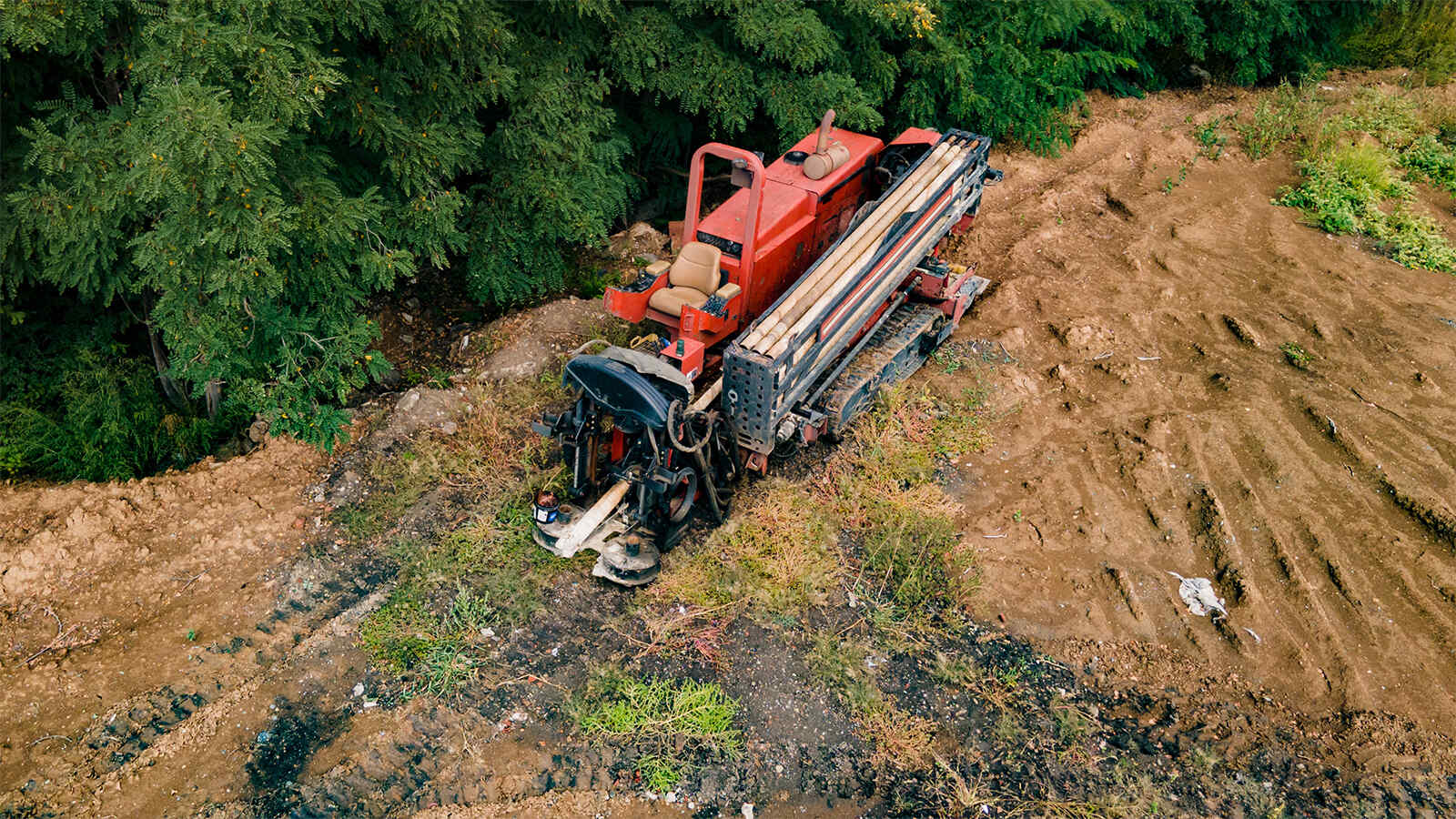
Most computer models that take into account cuttings size use a cuttings size of 0.25 inches (6 mm). Figure 1 shows the cuttings loading as a percentage of the total volume of the fluid in the bore as it relates to the pump output and the cuttings size using the properties of the "Normal Fluid". The small cuttings size which is representative of what might be encountered in well sorted sands and friable sandstone, indicates that there would not be a significant cuttings loading problem in the bore. As the cuttings size increases slightly, however, the increase in cuttings load becomes significant. The solids loading with the 0.3 inch (8 mm) cutting is so severe that the model indicates that severe cuttings beds Conventional wisdom in the HDD industry indicates that if a hole cleaning problem develops, an increase in viscosity will alleviate the problem.
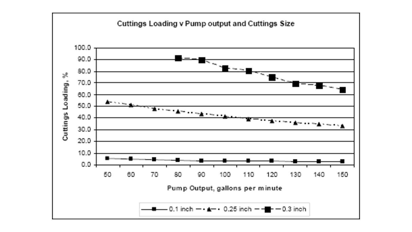
Figure 2 shows the results of modeling with the "Thicker Fluid" properties from Table 1. The modeling shows that the higher viscosity does indeed improve the cuttings loading in the bore, but at what price? In order to answer that question we have to look at the contribution of each component (fluid density, annular pressure loss, and cuttings loading) on the total pressure exerted on the bore.
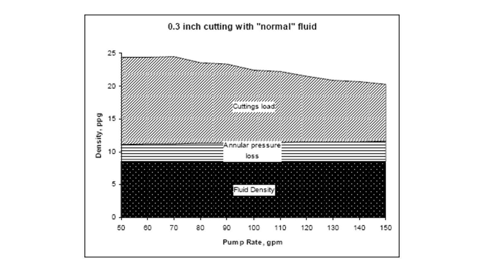
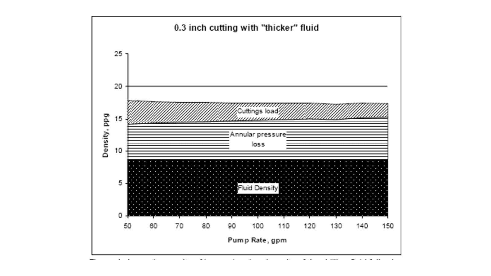
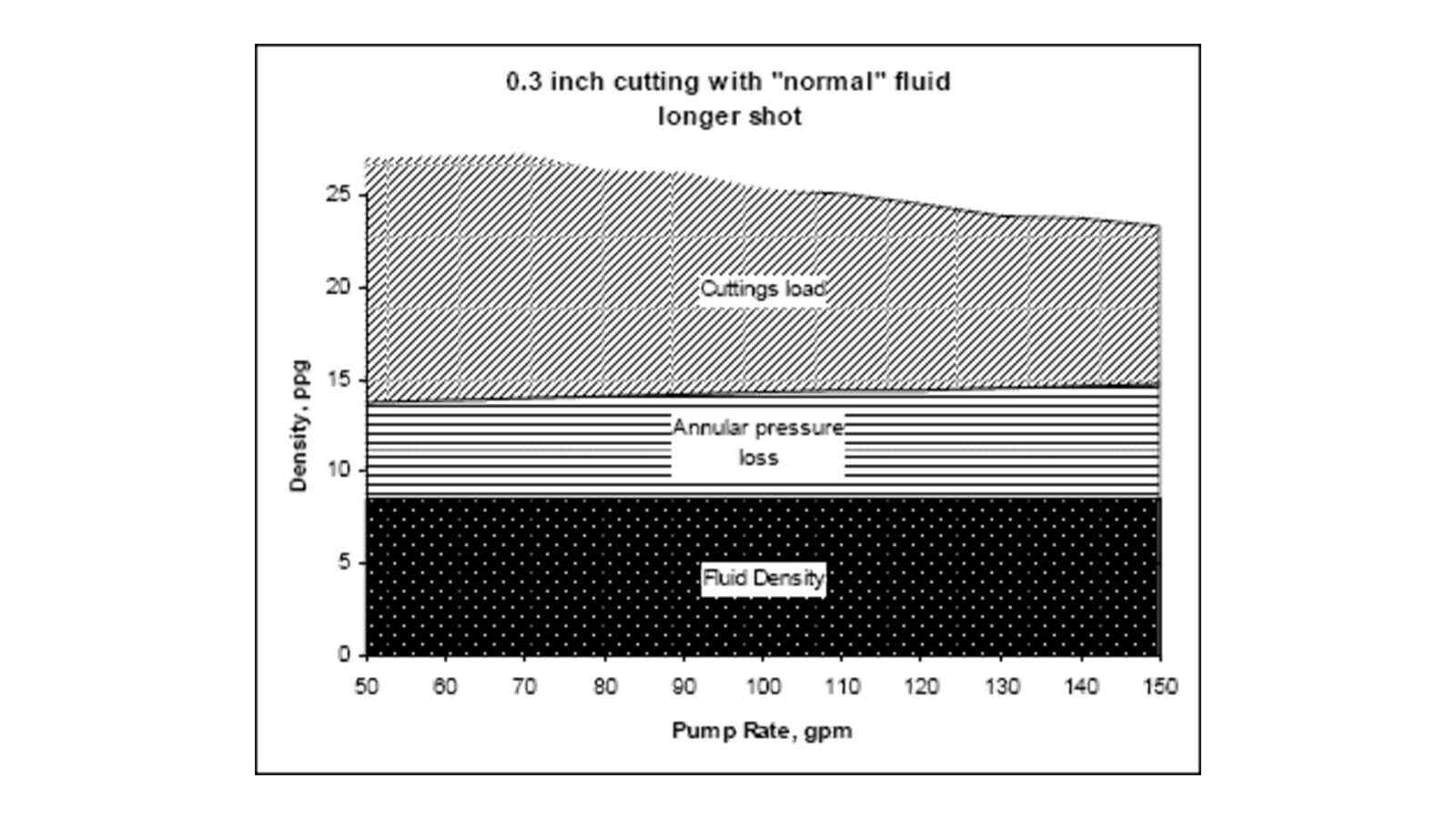
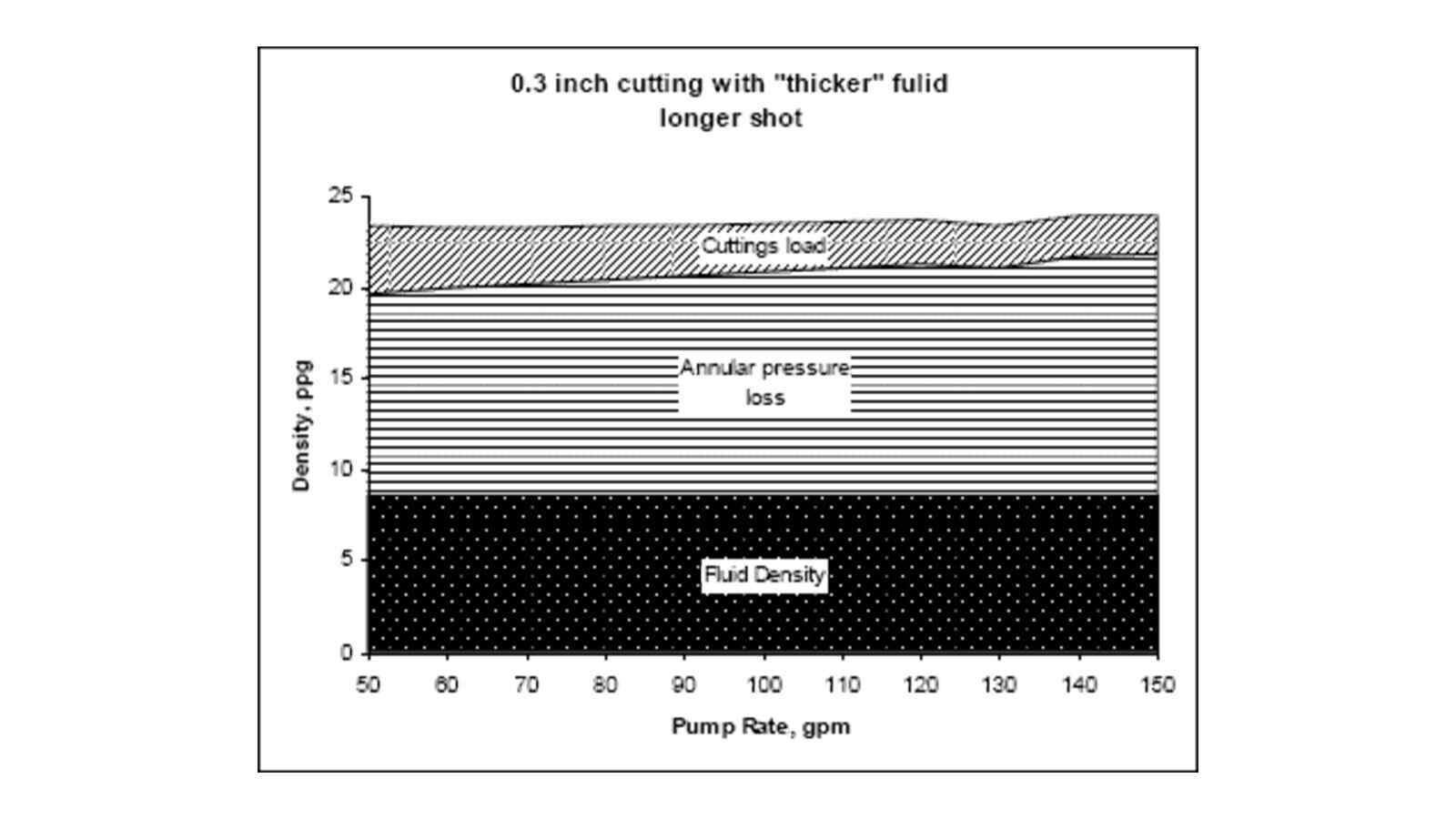
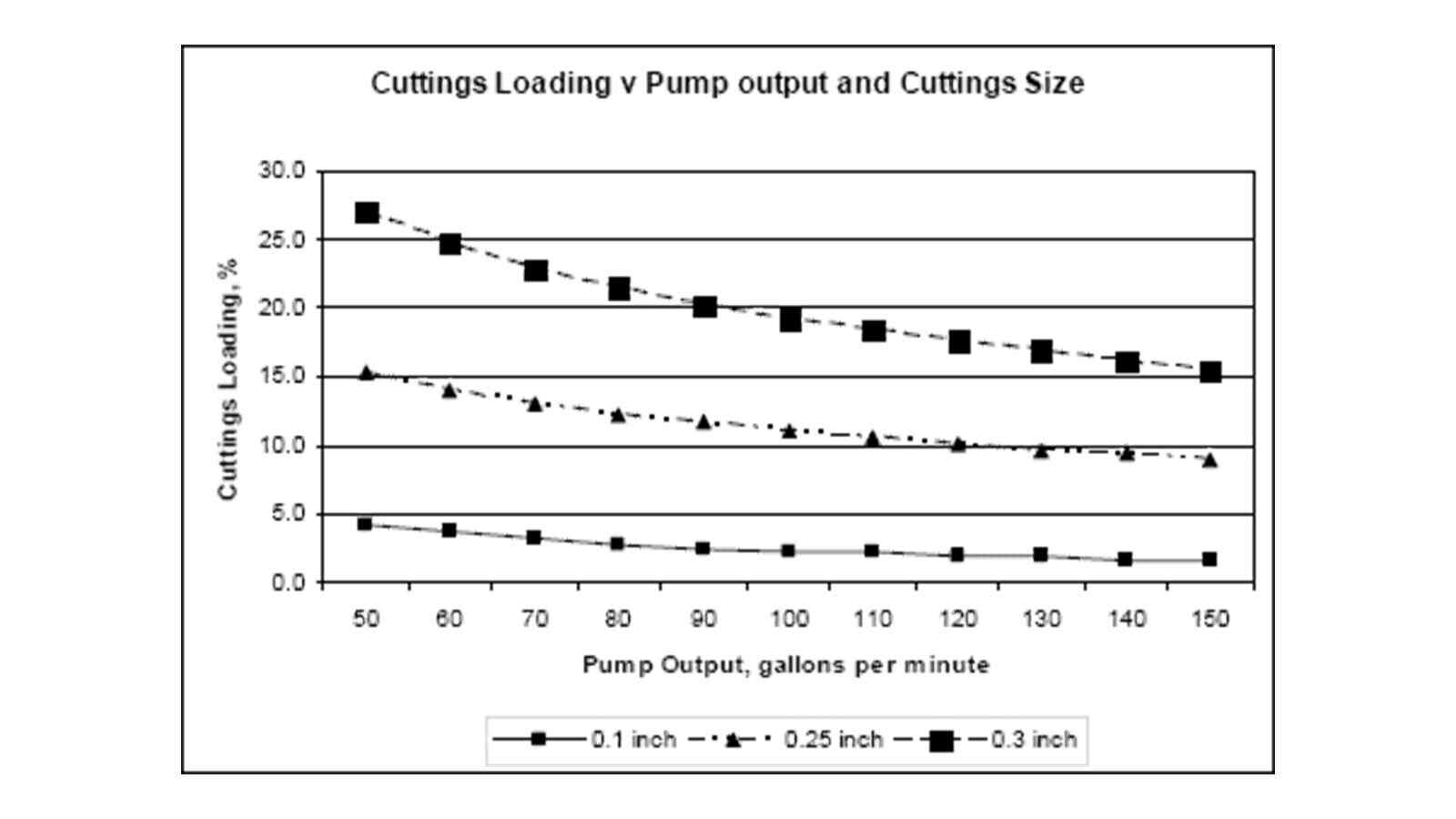
Figure 3 shows the contribution of the components to the total pressure exerted on the formation with the "Normal" fluid. The density of the fluid contributes a constant pressure across all flow rates, provided that the density remains the same. Because the fluid is relatively thin, the annular pressure losses are low and there is not a great deal of difference across the selected flow rates. The big difference is in the contribution of the cuttings load. The other significant item to note is that the cuttings load is reduced at higher flow rates. This indicates that the flow rate has not been optimized for cuttings loading at this configuration.
Figure 4 shows the results of increasing the viscosity of the drilling fluid following conventional wisdom. The increase in viscosity is relatively small but the increase in annular pressure loss is significant for a 100 foot (30.48 m) shot. When the length of the shot is increased to 1000 feet (304.8 m) and the depth of the shot is 50 feet (15.24 m), the magnitude of the problem becomes clearer.
Figure 5 shows the contributions of each of the components using the "normal" fluid with a longer shot. The annular pressure losses are still manageable but the cuttings loading is excessive.
Figure 6 shows the contribution of the increased viscosity to the annular pressure loss. The reduction of the effect of cuttings loading is offset by the increased annular pressure losses. The annular pressure losses have become a limiting factor for this shot. In many cases, the increase in viscosity is the least desirable approach due to the adverse effects on annular pressure loss. There are several other parameters that can be adjusted to modify the cuttings loading (Rate of Penetration, cuttings size, increased flow rate, etc).
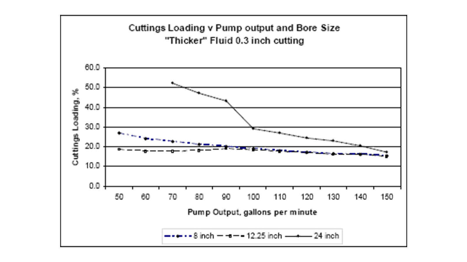
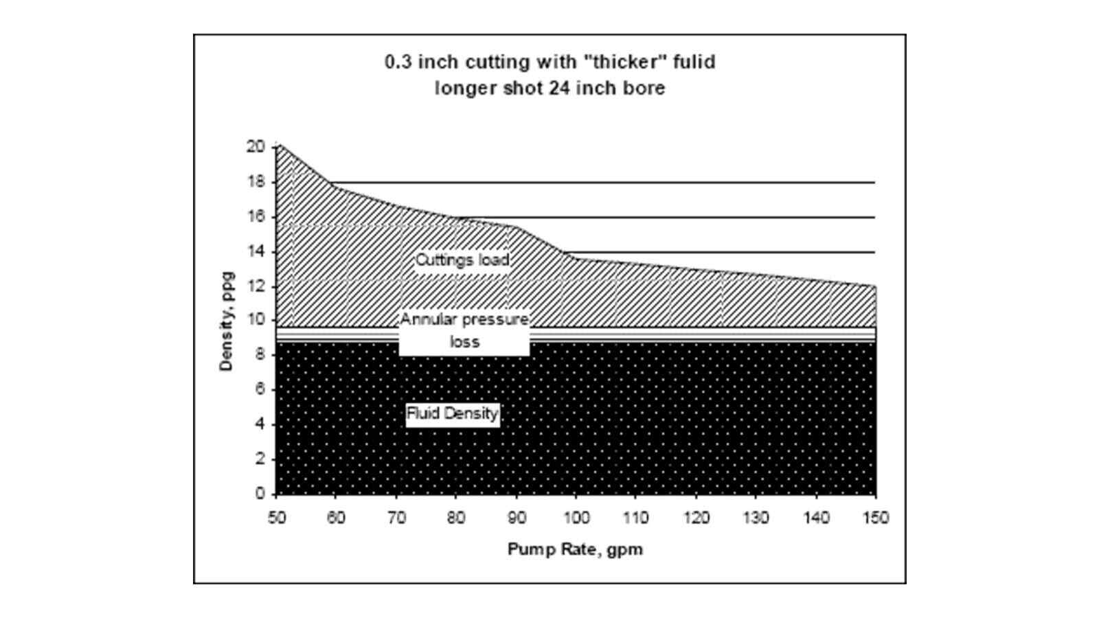
The effect of the diameter of the bore for the final ream on cuttings loading for the "Thicker" fluid is represented in Figure 7. For each set of fluid properties there is a boundary limit where the suspension characteristics of the fluid are not sufficient to entrain the cuttings and results in a rapid increase in cuttings loading. This limit is shown on the 24 inch hole between 90 and 100 gpm.
One of the most significant differences that occur in the larger reamed bores is the dramatic reduction in the annular pressure losses and their contribution to the total annular pressure. Comparing Figure 6 with Figure 8 gives an indication of the magnitude of the reduction of annular pressure loss between the 8 inch pilot and the 24 inch final ream.
While trends in the modeling exist, each bore will have different driving parameters and should be evaluated separately based on the limiting conditions. The limiting conditions may be mechanical, may be a result of the geological conditions encountered, or they may be from other sources. As indicated in the modeling of the annular pressure losses, limiting conditions may vary between the pilot hole and the final ream. The ability to identify these limiting factors and to determine alternatives or to modify drilling parameters prior to starting the bore is critical to the success of the project.
Computer modeling should be part of the preplanning and execution of critical bores to identify potential problems and eliminate or minimize the risks associated with inadvertent returns or frac outs. The use of computer modeling should take into account the effects of cutting loading since cuttings loading can contribute significantly to the total annular pressures in the bore.